
Lithium Battery SKD CKD One Stop Factory Solution
Build Your Local Energy Storage Business with Flexible CKD/SKD Solutions
GREEN ENERGY supports global partners in localizing energy storage manufacturing through configurable component kits, engineering support, and scalable assembly solutions—from SKD assembly to more extensive CKD manufacturing.
Universal CKD & SKD Lithium Battery Solutions for Global Integration
GREEN ENERGY provides comprehensive CKD and SKD lithium battery solutions for energy storage integrators, UPS manufacturers, and regional assembly partners. Our solutions are tailored to diverse technical specifications, manufacturing capabilities, and market requirements, supported by a factory-direct supply model and coordinated engineering services.
By offering flexible component supply configurations and technical support for local assembly, GREEN ENERGY helps partners develop localized manufacturing capabilities, optimize logistics and overall landed costs, and strengthen their competitiveness in regional markets. Our approach is designed to support scalable production and long-term cooperation across international markets.
Factory-Direct Supply
Factory-Direct Component Sourcing
Grade-A Cell Quality
Grade-A Lithium Battery Cells from Qualified Suppliers
Engineering Expertise
Extensive Battery Pack Engineering and Design Experience
Compliance & Verification
Component Compliance and Standards-Based Design Verification
Quality Assurance
Rigorous Component Inspection and Material Quality Control
Transport Documentation
Comprehensive Documentation for Dangerous Goods Transportation


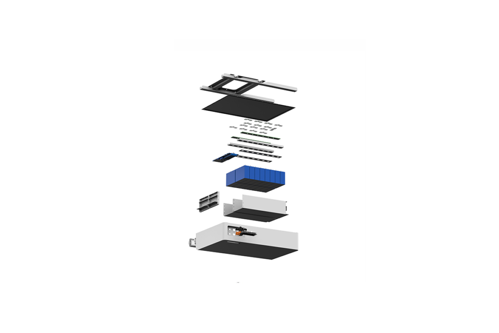


Note: CKD & SKD components can be supplied subsequent to product appearance design developed in accordance with requirements.
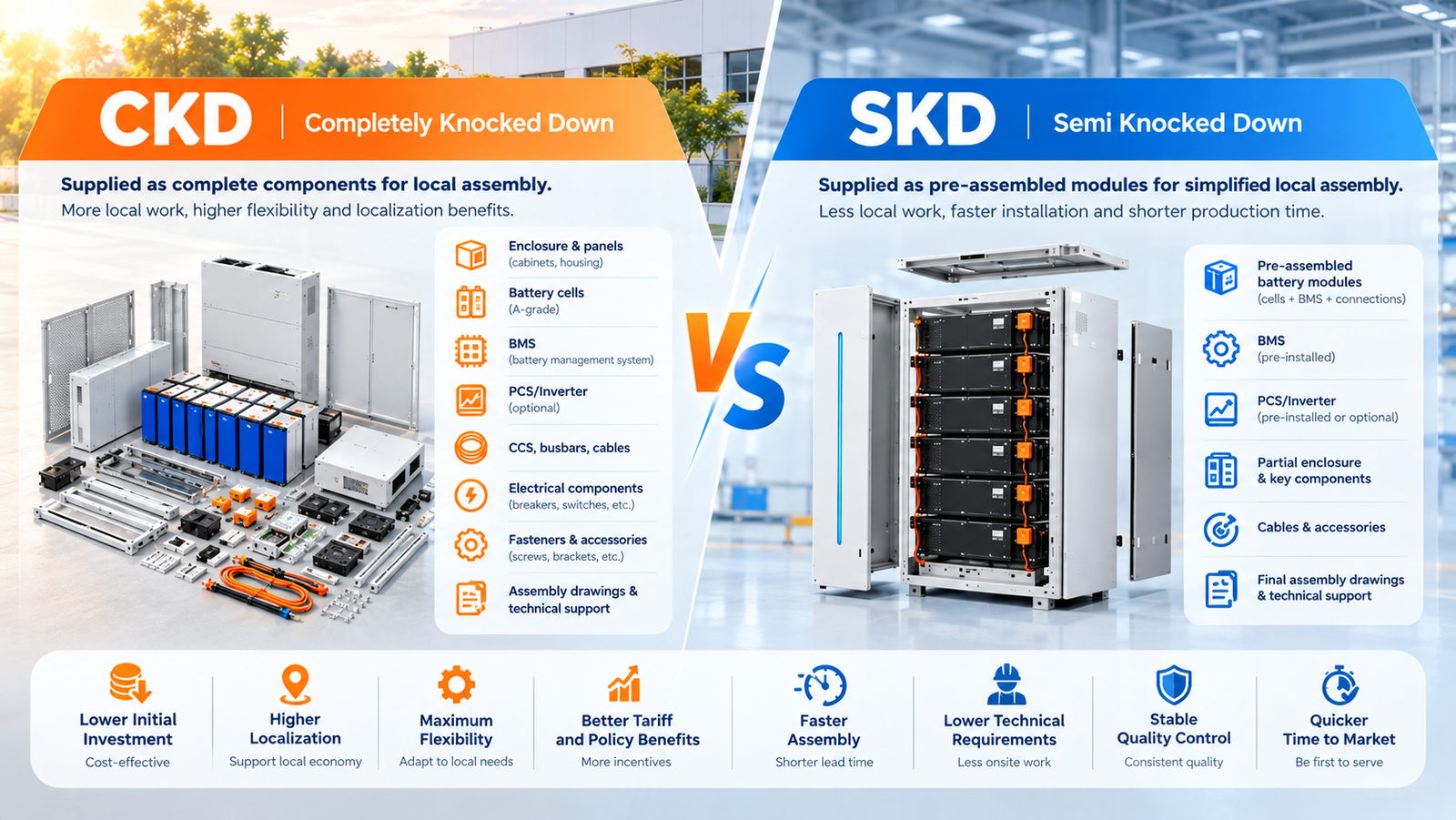
Battery Module Interconnection Technology
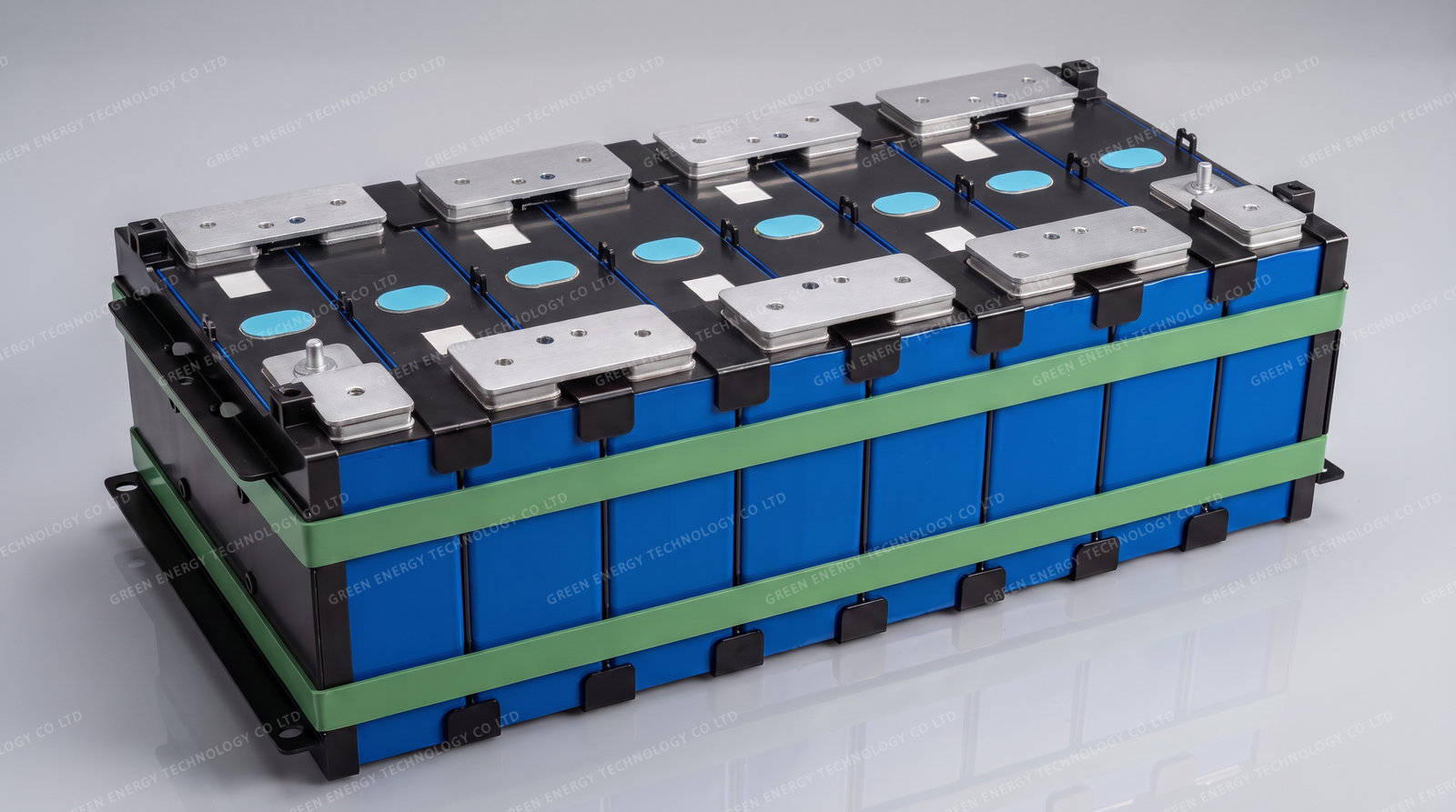
Traditional Battery Module Design
This established approach uses individual insulated wires to connect cell voltage and temperature sampling points to the BMS. The harness is assembled through processes such as wire cutting, stripping, terminal crimping or soldering, followed by connection to the BMS.
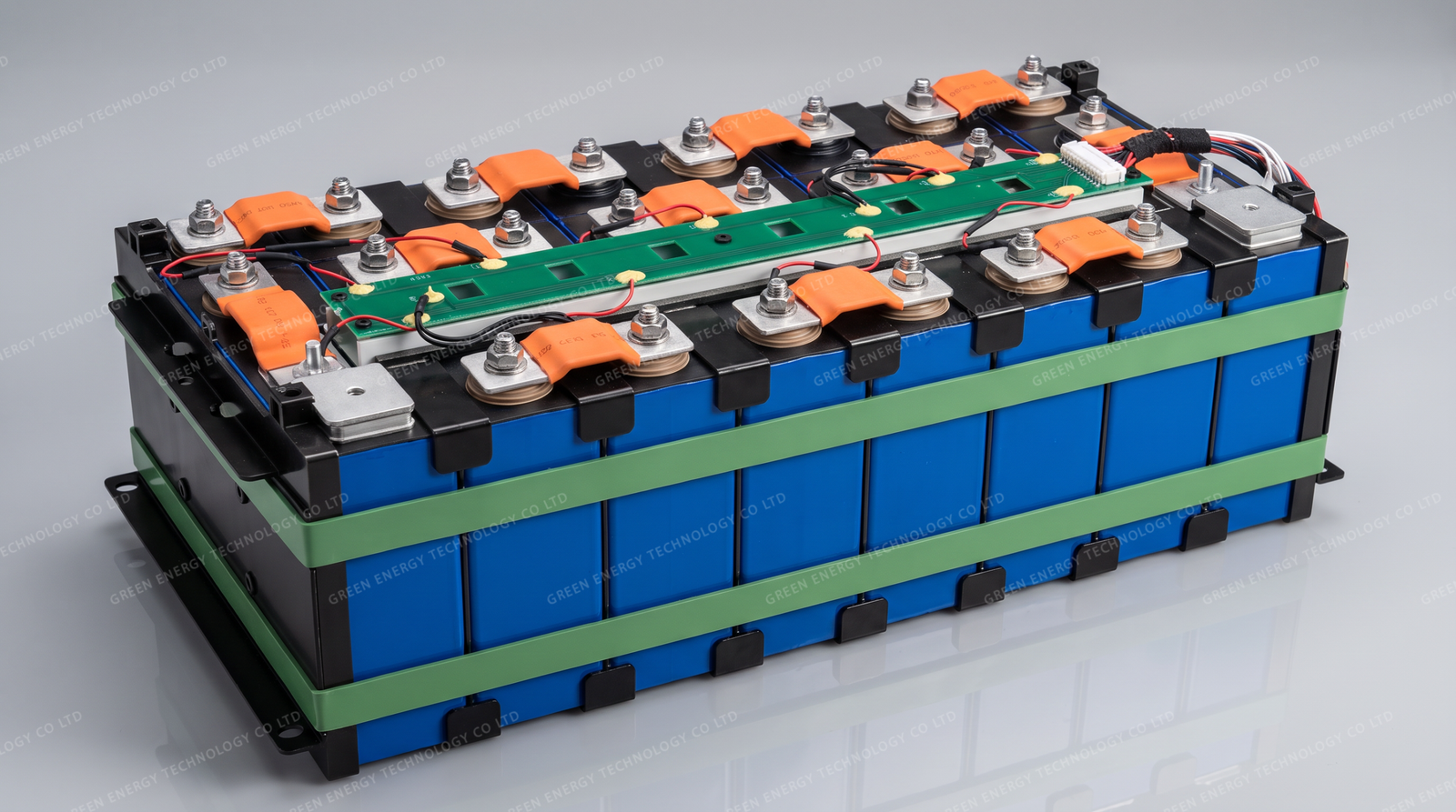
PCB-Based CCS Integrated Busbar Design
This design integrates cell voltage sampling circuits and NTC temperature sensors onto a rigid PCB, combined with busbars and supporting structures to form a compact Cell Connection System (CCS). Depending on the design, additional components such as fuses may also be integrated.

FFC-Based CCS design
This CCS configuration combines a sampling harness, sensing terminals, NTC temperature sensors, conductive aluminum busbars, and an injection-molded or thermoformed tray. The tray helps position and support the components, while the harness connects cell voltage and temperature sampling points to the BMS.
| Solution | Traditional Wiring Harness | PCB/Hard-board CCS | FFC Based CCS |
|---|---|---|---|
| Advantages | Simple structure and low material cost: wires and terminals are generic parts with low procurement barriers. | High integration: consolidates dispersed wiring, sensors and connectors into one board, saving over 30% space. | Excellent flexibility: can bend slightly with cell expansion, avoiding pad cracking risk caused by stress concentration. |
| Advantages | Flexible maintenance: a single damaged wire can be replaced locally without full assembly replacement. | Strong automation compatibility: works with SMT pick-and-place, AOI inspection and automated welding, greatly improving production efficiency and consistency. | Strong anti-interference: copper wires fully enclosed in insulating film offer better EMI shielding than exposed wires, suitable for high-noise battery environments. |
| Advantages | Mature technology: fully validated process with no new introduction risk. | High reliability: well-sealed circuits resist moisture, corrosion and oxidation, offering better long-term stability than exposed wiring. | Good automation compatibility: integrates with CCS production lines for high-precision vision positioning + automated welding, ensuring consistent solder joints and low rework rates. |
| Disadvantages | Large space occupation: stacked cable routing compresses internal cooling channels and reduces module packing efficiency. | Low design flexibility: changing sampling point positions or quantity requires new tooling and board fabrication, resulting in long iteration cycles. | Higher cost and longer customization cycle. |
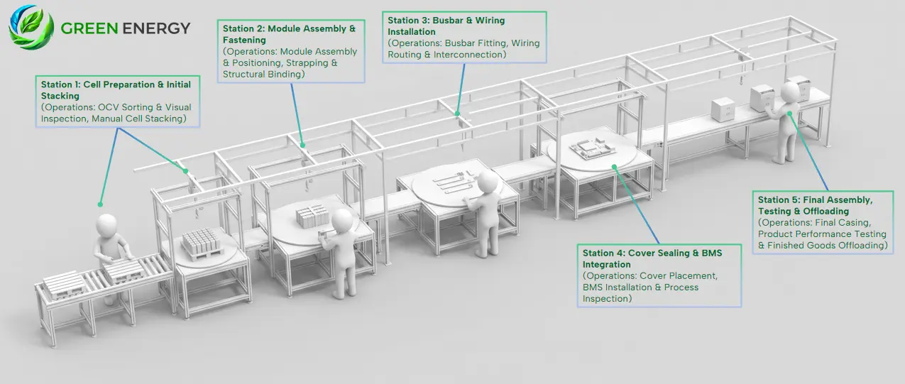
Battery System Manual Production Line
Five steps for manual assembly line
Cell Sorting & Manual Stacking Process
This foundational step involves OCV testing and visual inspection to ensure cell consistency. Qualified cells are then precisely stacked manually to prepare for module assembly.
Module Assembly & Structural Fastening
Stacked cells are assembled and aligned to form a robust battery module. Operators use specialized strapping to bind the structure, ensuring mechanical integrity and preventing displacement.
Busbar Fitting & Wiring Interconnection
Busbars are accurately installed onto cell terminals to establish series and parallel connections. Operators then perform precise wiring routing and interconnection to guarantee stable electrical transmission.
Cover Sealing & BMS Integration Process
The module cover is sealed, and the BMS is installed to enable state monitoring and safety management. A strict process inspection is conducted to verify correct installation and wiring connections.
Final Assembly & EOL Testing Process
This final quality gate involves completing the outer casing and conducting comprehensive performance tests. Qualified products are offloaded, ensuring meet 100% of factory release standards.
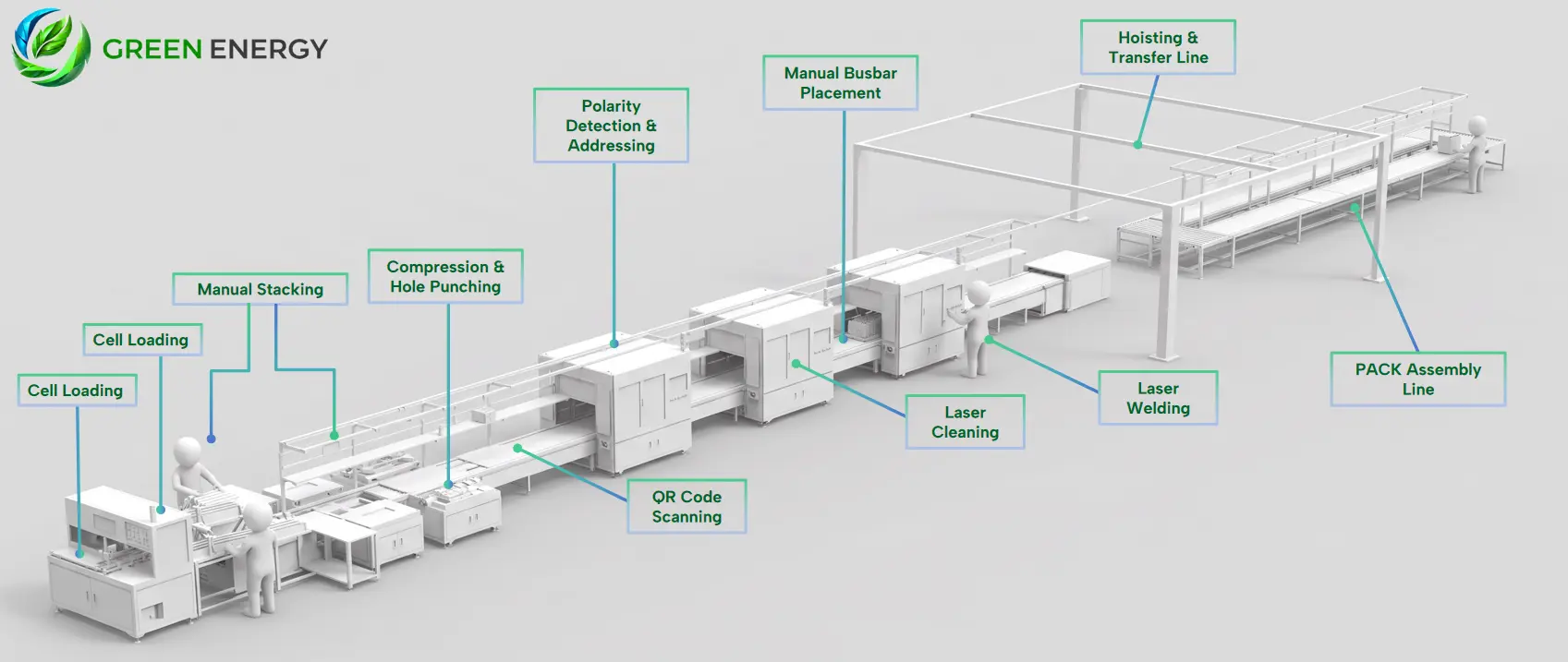
Semi-auto BESS Production Line
11 steps for manual assembly line
1 - Cell Loading
Automatic feeding of battery cells onto the production line
2 - OCV Sorting
Open Circuit Voltage testing and internal resistance
3 - Manual Stacking
Manual arrangement and stacking of cells into modules
4 - Hole Punching
Module compression and structural hole punching
5 - QR Code Scanning
Scanning cell QR codes for data tracking and binding
6 - Polarity Detection
Verifying positive/negative polarity and assigning addresses
7 - Laser Cleaning
Laser cleaning of welding surfaces to remove oxides) Manual Busbar Placement
8 - Manual Busbar Placement
Manual placement of busbars and connection pieces
9 - Laser Welding
High-power laser welding of busbars to cell terminals
10 - Hoisting & Transfer Line
Automated hoisting and transfer of modules between lines
11 - PACK Assembly Line
Final assembly of modules into the complete PACK system
Strategic Value & Service Ecosystem
GREEN ENERGY supports global partners with integrated products, engineering expertise, and manufacturing enablement.
Comprehensive Product Portfolio
Residential ESS, BESS, backup batterie—serving a wide range of energy storage applications.
Experienced Engineering Team
Engineering expertise and structured quality processes support reliable manufacturing and consistent production performance.
End-to-End Manufacturing Support
From product design to commissioning, and engineer training, we help partners establish and scale local manufacturing operations.
Trust and Worth
Our Clients